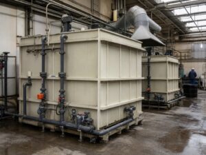
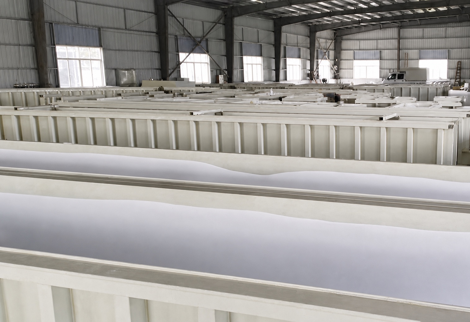
Specify PP tank supports and saddle interfaces before fabrication by defining the tank orientation, filled and empty load cases, support geometry, contact surface, restraint method, thermal movement, and responsibility split between the PP fabricator and the steel-support supplier. A support drawing should show how the tank is carried without creating point loads, forced connections, or inaccessible welds.
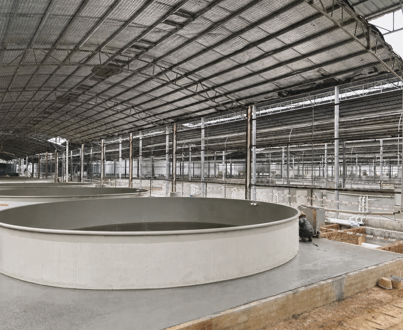
Treat the support as part of the tank design
For a fabricated PP tank, the support is part of the load path. Liquid weight, tank self-weight, piping reactions, wind or seismic actions where applicable, transport handling, test filling, and temperature-related movement can all influence the interface. A tank that looks stable when empty may deflect or concentrate load differently when full.
The EN 12573-1 standard reference is useful background for welded static, non-pressurised thermoplastic tanks, including PP. It does not replace the project calculation or prescribe one universal saddle shape. Treat the governing tank standard, engineer’s calculation, and approved support drawing as the acceptance basis.
QEEHUA’s practical review starts with one question: where does each reaction enter the PP shell, base, skirt, or reinforcing profile? If that path is not visible in the drawing, the fabricator cannot reliably decide where to place a stiffener, where to leave a sliding gap, or how to inspect the weld after the steel frame is installed.
Select the support arrangement before choosing interface details
Choose the support concept from the tank orientation and installation loads first. Do not copy a support from a visually similar vessel without checking the actual geometry and service duty.
| Support concept | When it may be considered | Specification inputs that must be fixed |
|---|---|---|
| Continuous flat base or slab | Vertical tanks or trays carried over a prepared, level surface | Base flatness, bearing area, drainage, liner, edge clearance, and whether the tank can slide as it expands. |
| Skirt or ring support | Vertical round tanks where a continuous perimeter reaction is part of the approved design | Ring elevation, shell transition, weld access, stiffening, inspection openings, and anchoring arrangement. |
| Two or more saddles | Horizontal cylindrical tanks or equipment that transfers load through discrete cradle locations | Saddle centerlines, contact profile, width, pad or liner, spacing, end clearances, restraint, and pipe-nozzle coordination. |
| Independent steel frame with local PP details | Equipment that needs a raised working level, access clearance, or a separate seismic/transport frame | Frame datum, load-transfer points, sliding or hold-down detail, removable access, and responsibility for final alignment. |
| Bund or secondary-containment support | Tanks installed inside a PP-lined or fabricated containment area | Drain path, cleaning access, support-foot protection, liner compatibility, and spill inspection visibility. |
These are design options, not a catalogue of approved QEEHUA constructions. The project engineer should confirm which arrangement is suitable before fabrication. A PP tank support specification should identify the selected concept and explicitly reject alternatives that would overload the wall or block maintenance access.
Define the saddle interface on the drawing
“Saddle support” is incomplete unless the contact geometry is documented. The drawing should show the tank outside diameter or profile used for the interface, saddle centerlines, support spacing, contact arc or seat profile, support width, edge distances, and the elevation datum used by the installation team.
| Interface item | What to specify | Fabrication or installation risk if omitted |
|---|---|---|
| Contact surface | Continuous, smooth, correctly profiled bearing surface with the approved pad, liner, or wear layer | Point loading, local indentation, abrasion, or a hard edge touching the PP shell. |
| Support location | Centerline, spacing, end clearance, and relation to seams, nozzles, manways, and stiffeners | Reaction falling on a weak panel, weld intersection, opening, or inaccessible inspection zone. |
| Restraint | Hold-down, lateral guide, anchor, or deliberate sliding detail with its direction of restraint | Thermal movement is blocked, or the tank can shift during filling, testing, or handling. |
| Access | Clearance for visual inspection, cleaning, drain-down, bolt access, and later repair | The support hides the weld or makes a leak path impossible to inspect after installation. |
| Interface responsibility | Steel fabricator, PP fabricator, installer, and approving engineer identified for each detail | Gaps between scopes lead to forced fit-up, unapproved drilling, or field welding. |
Do not insert a universal contact-angle or saddle-width value into an RFQ without a calculation. The correct value depends on the shell geometry, liquid head, support stiffness, temperature, and the project safety factor. Ask the supplier to return a marked support drawing or interface schedule for approval.
Separate steel support behavior from PP shell fabrication
Many support failures begin when the steel frame and PP shell are treated as one rigid material. PP and steel do not respond identically to temperature or restraint. The detail must show whether the tank is fixed, guided, or allowed to slide in a defined direction, and where the reaction is intentionally transferred.
Specify smooth radii, protected edges, and a compatible bearing layer where the PP touches steel or another hard surface. A pad is not a substitute for a correctly profiled saddle: it should not create a new ridge, trap liquid, or creep out of position during service. If a PP wear strip, channel, gusset, or local doubler is proposed, identify its material, thickness, weld access, and inspection method on the same detail.
The DVS thermoplastic-tank calculation reference illustrates why tank geometry, reinforcement, and load cases belong in a calculation rather than a generic support rule. Check the current edition and applicability with the responsible engineer; the reference is not a QEEHUA design approval.
Coordinate saddles with seams, nozzles, drains, and stiffeners
Before releasing the support detail, overlay it on the tank fabrication drawing and joint map. Check the saddle against shell seams, bottom-to-wall welds, baffles, nozzles, drain outlets, overflow lines, manways, lifting points, and any stiffening channel. A support that is structurally adequate can still be a poor fabrication detail if it blocks a weld or leaves no route for inspection.
Pay special attention to bottom drains and low points. A support foot or cross-member should not create a trapped pocket that prevents full drain-down or cleaning. For chemical service, keep the bearing and containment arrangement compatible with the specified cleaning and rinse procedure; do not assume that a generic rubber pad is suitable for every service.
Use the PP chemical-tank selection guide when confirming service conditions, and link the interface schedule to the PP tank RFQ checklist so dimensions, supports, nozzles, and acceptance documents remain consistent from quotation through fabrication.
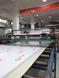
Process reference: this QEEHUA clip shows a PP sheet pendulum-impact verification process. It is relevant to the material traceability conversation behind a fabricated tank support detail, but it does not establish saddle dimensions, structural capacity, or installation acceptance.
Video reference: PP Sheet Pendulum Impact Test | QEEHUA Lab Quality Verification. This is a general material-verification reference, not a support calculation or saddle-interface approval.
Document the load cases and the acceptance evidence
Ask for the load cases that govern the support, not only a final support sketch. Depending on the installation, the design review may need to consider:
- Empty tank, operating fill, and specified test or commissioning fill.
- Tank self-weight, contents, covers, baffles, lining, mixers, and attached accessories.
- Pipe, valve, hose, or flexible-connection reactions that the tank nozzle should or should not carry.
- Wind, seismic, transport, lifting, or installation loads where the project requires them.
- Temperature-related movement and the direction in which the tank is permitted to slide.
- Local reactions at saddles, skirt rings, feet, hold-downs, and any PP reinforcing profile.
Record the design drawing revision, calculation reference, support material, bearing-layer identification, inspection hold points, and installation tolerances. During fit-up, photograph the support contact and record any shim, gap, field modification, or forced pipe alignment. A field change should trigger engineering review before the tank is filled.
For the weld condition and release package, link the support review to the PP tank weld inspection checklist. The support interface does not replace a weld inspection, dimensional check, or leak test; it connects those checks to the actual installed load path.
What to include in a PP tank supports and saddle interfaces RFQ
Give the fabricator and steel-support supplier one coordinated input package. At minimum, include:
- Tank orientation, overall dimensions, working capacity, service liquid, temperature range, and operating level.
- Approved tank drawing with datum, shell thickness zones, seams, openings, baffles, drains, overflow, and stiffeners.
- Support concept, locations, spacing, reaction directions, restraint points, and allowable sliding direction.
- Saddle or bearing profile, support width, pad or liner requirement, edge protection, and drainage provisions.
- Pipe and accessory loads, installation sequence, lifting or transport condition, and any seismic or wind design basis.
- Responsibility matrix for the PP fabricator, steel supplier, installer, inspector, and approving engineer.
- Required submittals: calculation note, interface drawing, material identification, weld map, dimensional report, and as-installed photographs.
The PP sheet selection, fabrication, and applications hub provides the wider material and fabrication context. Use it alongside the project drawing; it is not a substitute for support calculations or a customer-approved interface detail.
Final review before the PP tank is released for fabrication
Before approving the shop drawing, confirm that the support and saddle detail answers these questions:
- Where does the full operating and test load enter the tank?
- Is the contact surface continuous, smooth, profiled, and protected from point loading?
- Can the tank move in the intended direction without losing stability?
- Are supports clear of seams, drains, nozzles, baffles, and required inspection zones?
- Can the tank be drained, cleaned, repaired, and inspected after installation?
- Are steel, PP, liner, fastener, and field-modification responsibilities assigned?
- Are the calculation, drawing revision, hold points, and acceptance records listed?
A support sketch alone does not prove tank adequacy. Final suitability depends on the approved design, service conditions, loads, material selection, fabrication procedure, installation tolerances, and responsible engineer’s acceptance.
Frequently asked questions
Can a PP tank be placed directly on a steel saddle?
Only when the approved design defines the contact profile, bearing layer, edge protection, restraint, and load path. A bare or sharp steel edge can create local stress, abrasion, or a trapped-liquid problem; do not assume a generic saddle is suitable.
Should PP tank saddles be welded to the shell?
Not by default. A welded PP detail may be appropriate only when it is part of the engineered tank design, uses an approved fabrication procedure, and preserves inspection access and thermal movement. Many projects separate the structural steel support from the PP shell and define a controlled bearing or guide interface.
What information does a support drawing need before fabrication?
It should show tank orientation, datum, support locations, spacing, contact profile, pad or liner, restraint direction, clearances, pipe and nozzle coordination, load cases, material responsibilities, inspection access, and required calculation or approval documents.
How should saddle changes be handled after fabrication starts?
Stop the affected work, mark the change on the controlled drawing, review the new load path and clearances, and obtain engineering approval before drilling, heating, welding, shimming, or forcing connected pipework. Record the change and the as-installed condition in the handover package.
Send the tank drawing, service conditions, support sketch, load assumptions, and required handover format through the QEEHUA contact page. We can review the PP sheet and fabricated interface against the project requirement before fabrication.